
Authors: Michel and Gernot
The following DIY manual describes an easy-to-implement battery backup module for the BeagleBone Black. This can be useful in certain applications, such as out-door usage where constant power is not present and it is not desirable to just drop power on the BBB board. It was built for a RasPBX setup with the motivation to have a safely powered BBB in all situations. The BBB is unfortunately suceptible to slowly rising supply voltage when powered on. Therefore it didn’t sometimes boot at all, which can be a serious problem after a power glitch. On top, voltage irregularities can cause the device to crash as well.
The battery backup can be applied to any BBB installation, running RasPBX, the original Anstrom Linux or any other distribution. However, USB devices cannot be used while running on battery, as the UPS does not power the USB host port. Take care that some distributions version will automatically shutdown a battery connected BeagleBone Black when power outage occurs. It might be the case with both Angström and Debian distributions available here. It happens with the “lxde” Debian version. If applicable, when running a standalone system 24/24, use instead the console version of the distribution. Debian console version works fine and is available here . By the way, if power outage lasts more than UPS battery life, data corruption may also arise (abrupt breakdown). Pehr Lorand Hovey developed a very interesting project. It may interest tinkerers who want to correctly shutdown their BBB running on battery after power outage. Here is the link to Pehr Lorand Hovey’s python scripts: BBB Safe Shutdown
The 1950 mAh Li-Ion battery used in this example keeps the board powered for more then 6 hours when running idle most of the time. It is currently in stock for around 36 Euros at Farnell.
The instructions are based on Shabaz’ work documented on Element 14, and have been slightly modified with a different circuitry and used battery type.
WARNING: The modifications presented here can destroy your BBB when not done carefully! The authors of this article are not responsible for any hardware defects that might occur when implementing these modifications. BeagleBone Black power supply MUST be removed before working on it
Another BeagleBone UPS with more simple components is described further down in this topic. In this other small projet 2 leads battery is used instead of 3 leads battery. A Bill of Material is also available. After checking this main tutorial, it is perhaps interesting to have a look at this other small tutorial
Tools
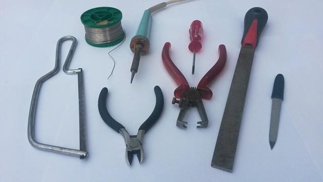
- Saw
- Solder wire
- Side cutter
- Soldering iron
- Wire stripper
- Screwdriver
- Metal file
- Nail file
Bill of Material
 Lithium-ion batteries from Panasonic including NTC, leads and JST connector are available with the following nominal capacity:
1200 mAh (Panasonic CGA-633450)—-> not anymore sold by Farnell- 1950 mAh (Panasonic CGA-103450)
Make sure to buy one of the batteries described in these data sheets: 1200 mAh, 1950 mAh
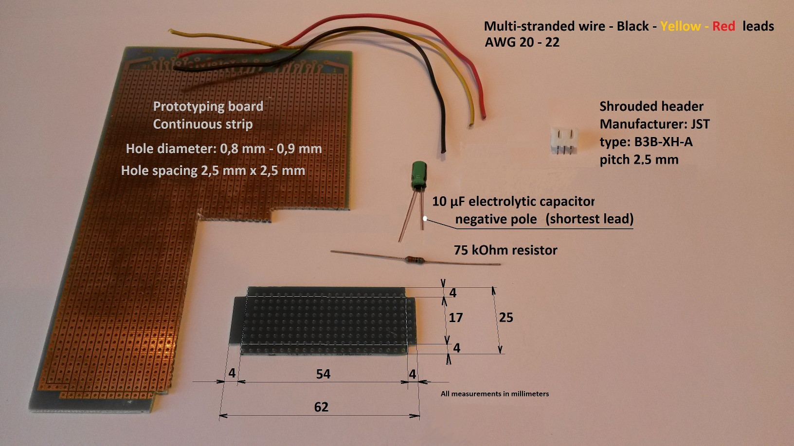
The small prototyping board has been built with a saw and a metal file. All components are generally available in local electronic stores (not the Li-ion battery). The multi-stranded wires were taken from an old defective PC power supply.
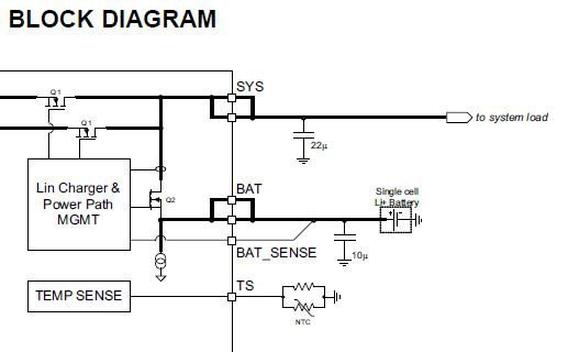
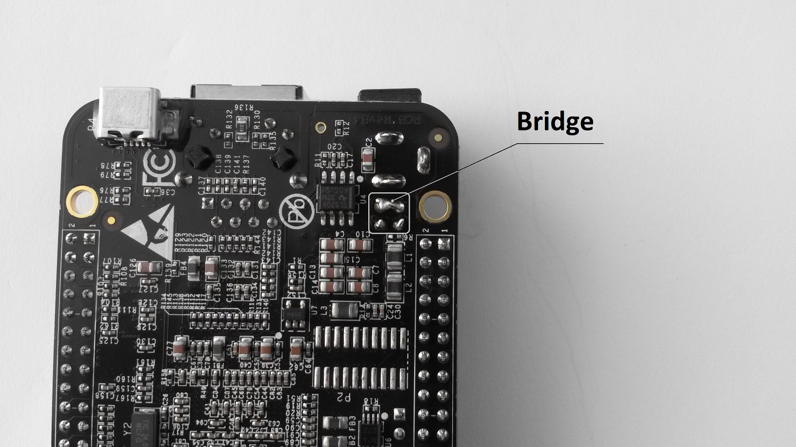
This is a part of the Texas Instruments TPS65217C block diagram. A bridge between BAT and BAT_SENSE must be soldered on the BBB board.
HOW TO

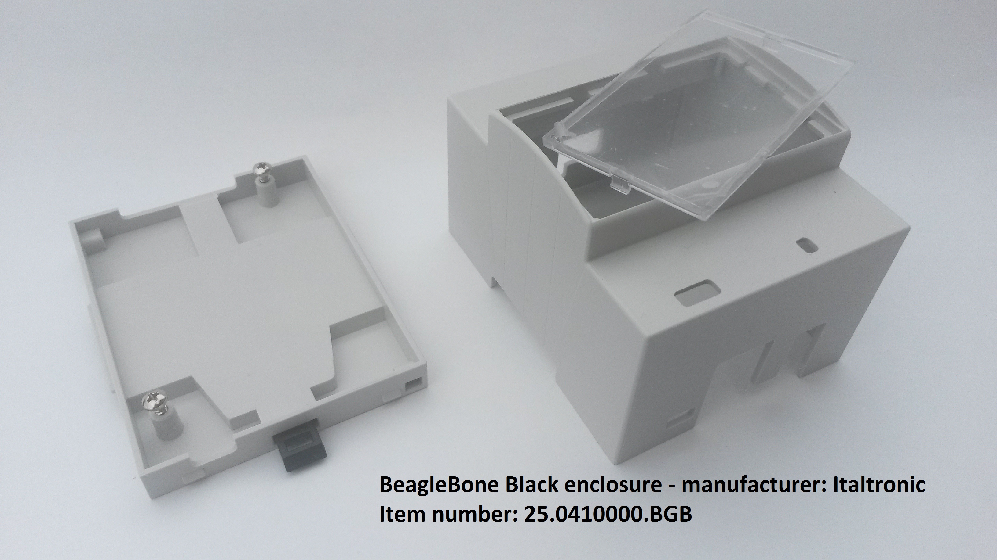
The used Adafruit enclosure needs to be modified as shown. Cut off acrylic sheets of
this particular enclosure at the sides. To protect the acrylic sheets during the job, leave the brown adhesive paper on. The red hatched parts need to be removed.
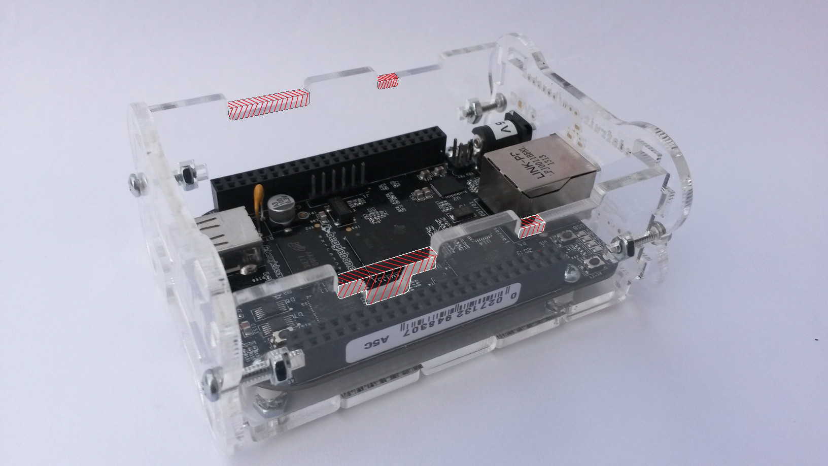
If the enclosure and the BBB are already mounted, it is safe to disassemble them and prepare the enclosure sides as described (see red marks).

This shows the modified enclosure and the BBB reassembled without top cover.
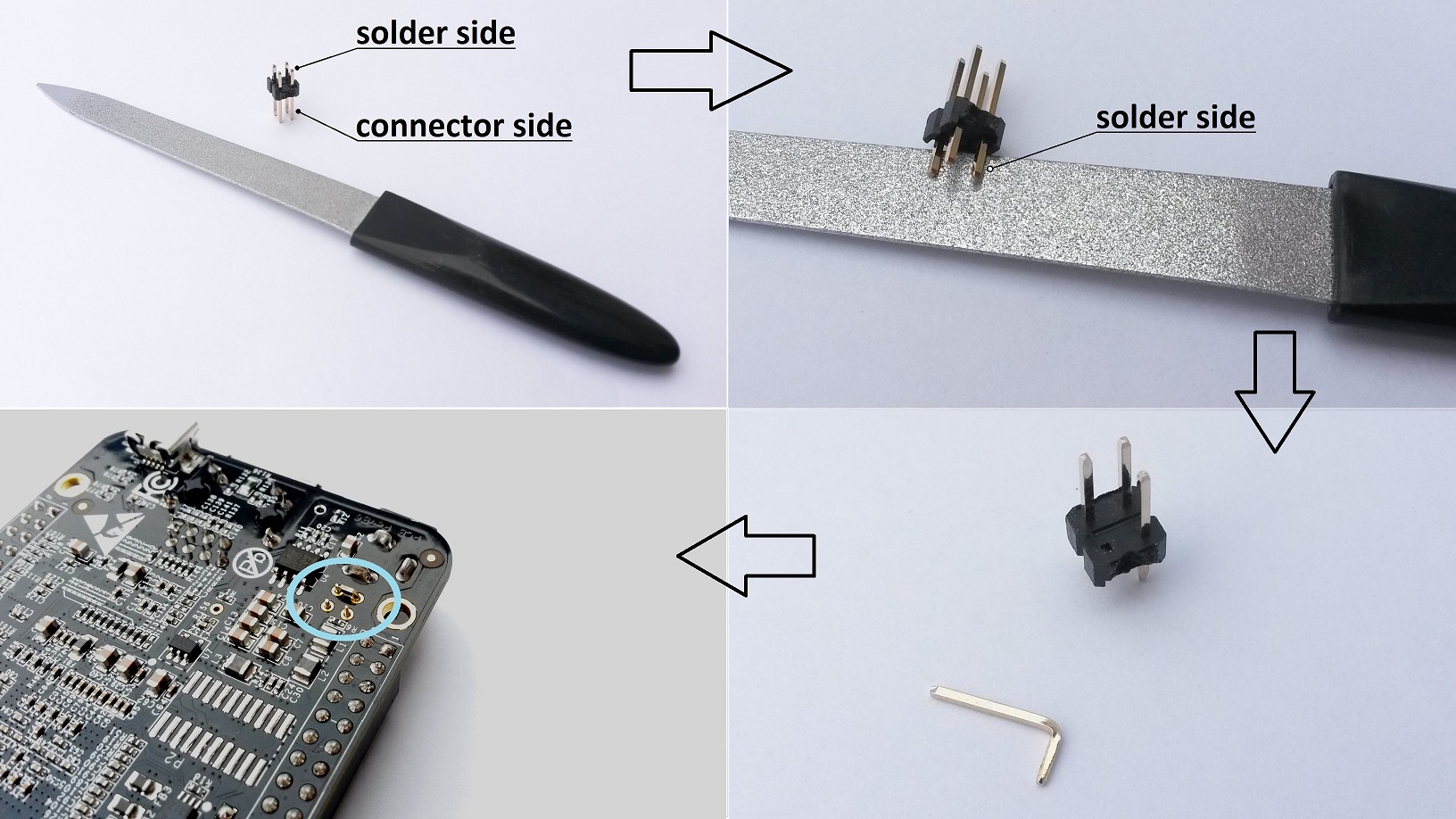
Throughout this DIY tutorial, a crimp housing is shown on most pictures. It connects the small electronic board to the BeagleBone Black. Nevertheless crimp sockets need a good crimp tool to be correctly fastened on each wire. A good crimp tool is expensive. To build a suitable connector, a cheaper solution exists.
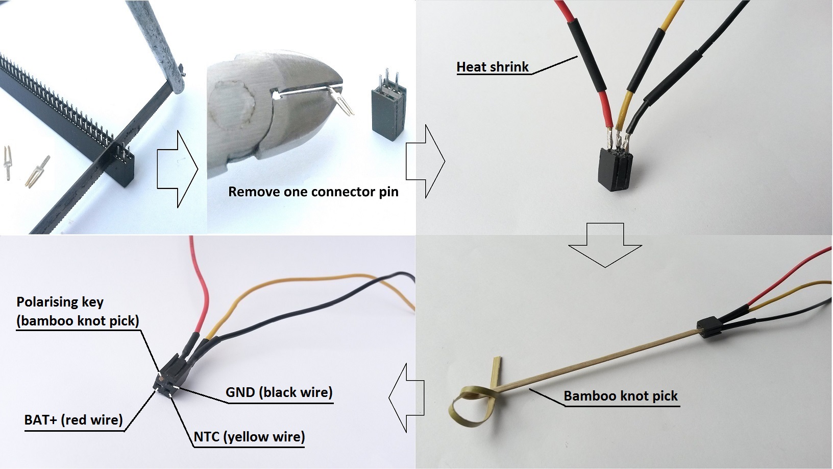
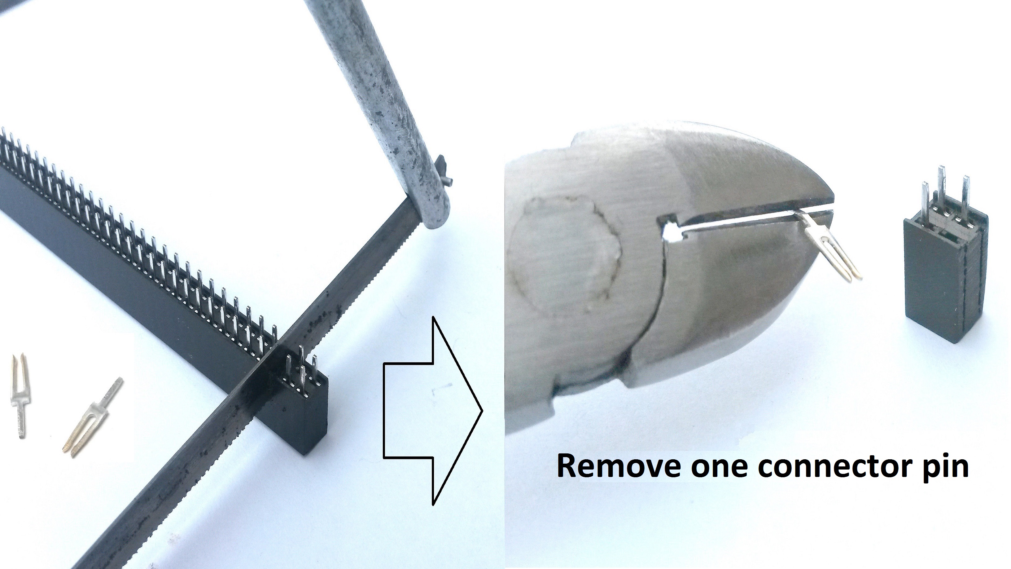
Small “2×2 way” connectors are rarely sold in electronic shops (I mean tiny connectors matching the small place available on the BeagleBone Black). But expansion connectors similar to those on the BeagleBone can often be found in these shops. That kind of connector may be cut, with a small saw, to build a “2×2 way” connector. Stranded wires can than be soldered on connector pins. The above picture shows different steps to achieve this task. A wood toothpick or better a bamboo knot pick with some glue at one end is a convenient polarising key. A metal file can help getting the right bamboo pick size if it is too large to fit in the connector.
ADVICE: Socket pins easily fit in BBB TP5, TP7, TP8 holes and header pins not.
Unhappily header pins will need to be slightly modified to fit in these holes…with a nail file. I discourage soldering the small black socket onto BBB board and mating header onto stranded wires. If this method is used, the header, powered by battery voltage, could inadvertently touch components on the BBB board and destroy them. The small black socket is at least isolated. It is safer to connect it to the coloured stranded wires.
Tinkerers, who anyway want to use Harwin crimp housing shown in the following picture and preferably already own the right crimp tool, have to purchase Harwin M20-003 polarising key and Harwin crimp socket M20-1180042. In this case use 22AWG wire. 20AWG wire won’t fit in crimp housing. By the way, Harwin crimp tool M20 series Z20-320 costs 312,85 EUR. The whole black connector seen on the upper left corner of the previous picture costs less than 1,00 EUR !
Before soldering components, verify that no tiny copper parts may fall from the small board onto the BBB when installed (possible damage!!). If necessary, use the metal file to carefully remove copper parts that the saw didn’t correctly cut. Clean the board when done.
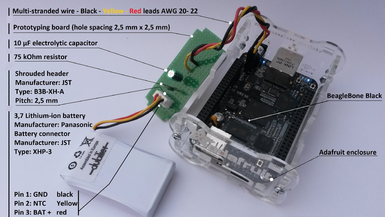
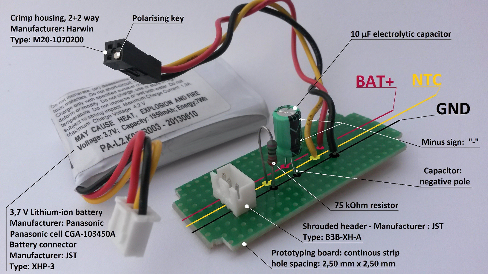
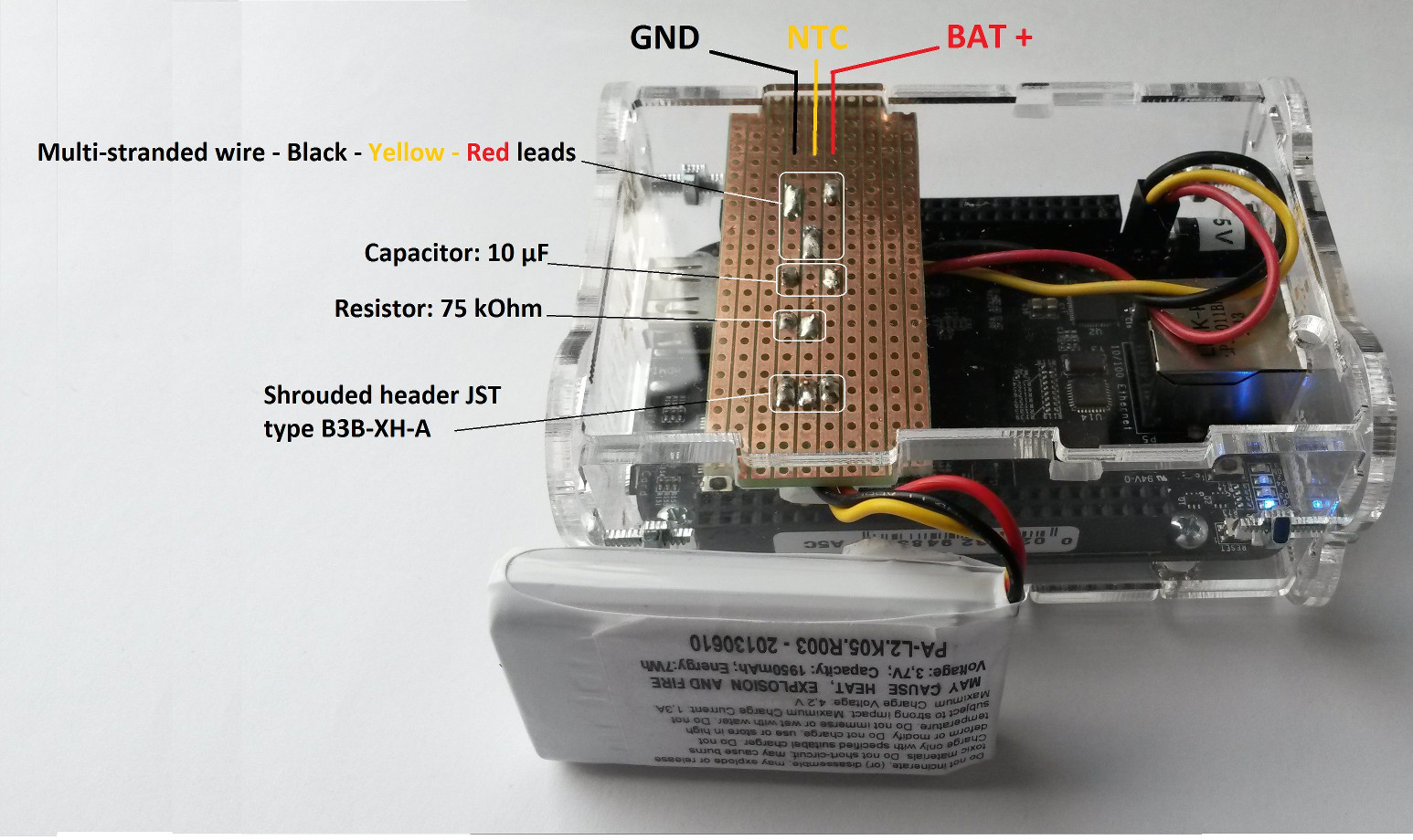
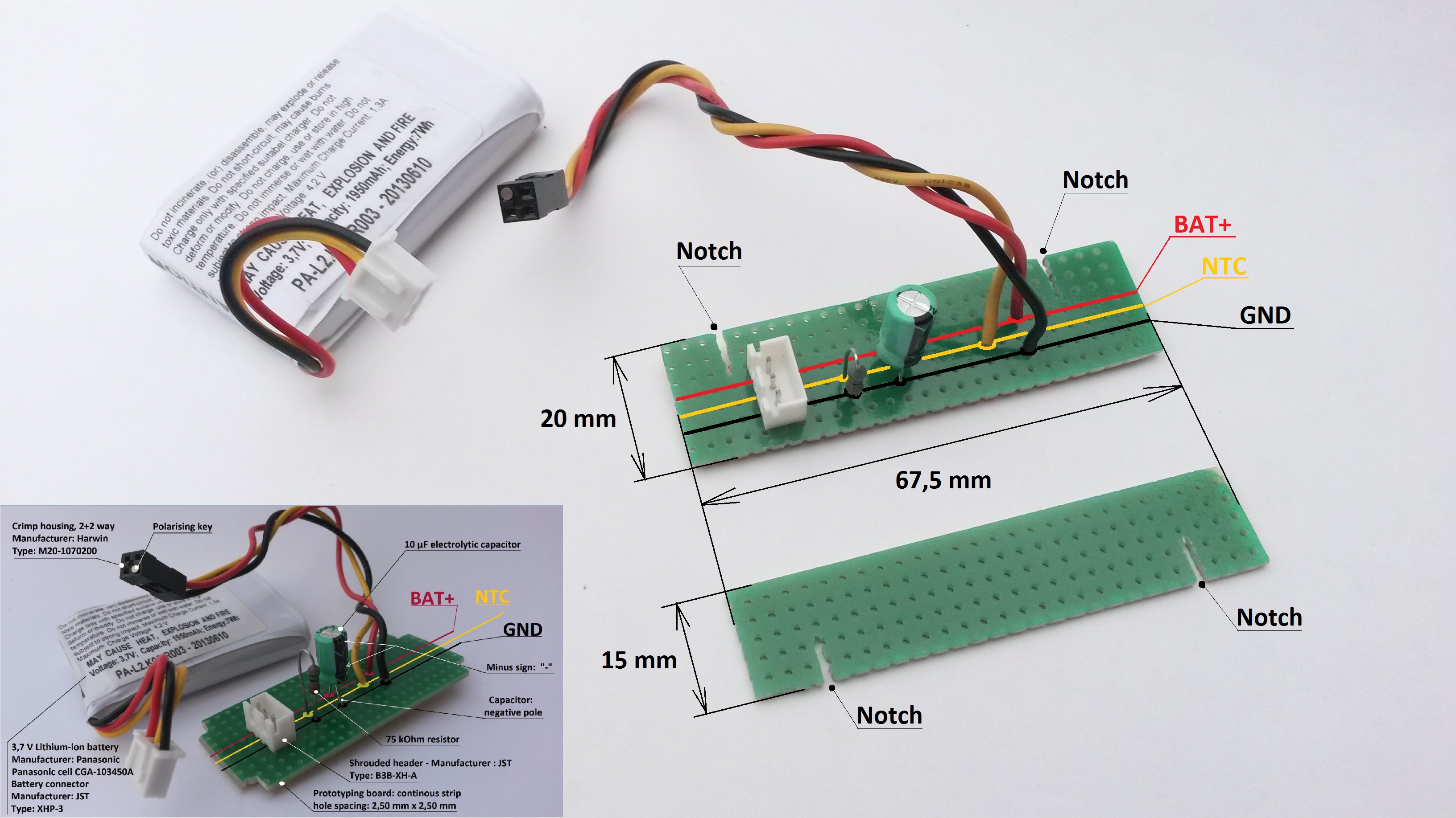
The components (connector, capacitor, resistor and coloured leads) must be placed along the copper strips parallel to the coloured lines as shown. Also have a look at the solder side further down.
CAUTION: Set the shrouded header in the same position as the picture displays it. When battery connector is plugged into the JST shrouded header, the coloured leads must match the coloured strips as shown. Incorrect header positioning will damage your BBB! The electrolytic capacitor is polarised. Its negative pole needs to be connected to the “GND” copper strip. The shortest lead connected to the capacitor body is the negative pole. Take a look at one of the previous pictures to avoid wrong insertion. Watch the small minus sign on the capacitor side to clearly identify it’s negative pole. Magnify the picture if necessary.
When the small board is built, its leads have to be connected to BeagleBone Black board with a header and matching connector. This latest was built in one of the previous steps.
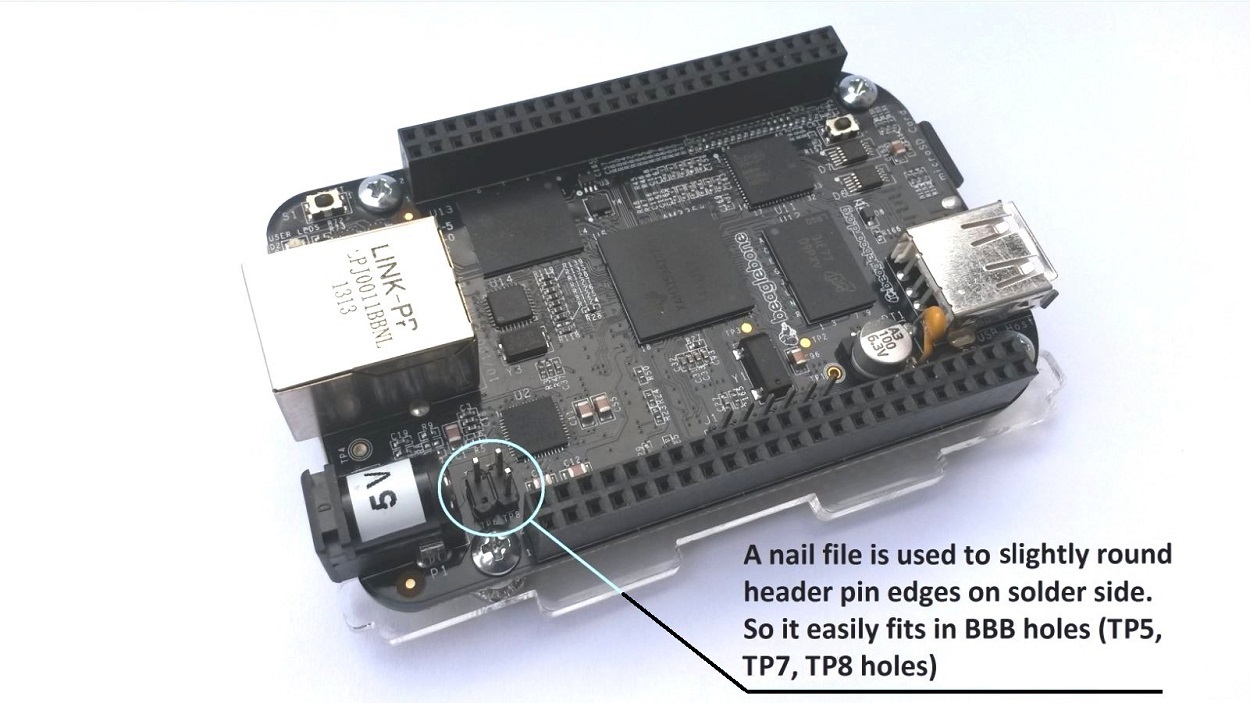
Unhappily, headers from electronic stores have too large pin size to fit in BeagleBone TP5, TP7 and TP8 holes. Therefore a nail file is used to carefully file away pin edges before inserting the header. It’s easier to keep the four pins on the black header housing when doing this job. In this case two pin edges may be filed away at the same time with correct filing angle. All other edges need to be filed away one by one. From time to time during this job, it can be proceeded to insertion test in BBB holes. When done, remove one header pin, bend it and resize it to suit distance between two holes. It will build the bridge between BAT and BAT_SENSE described on the block diagram. These parts are then inserted in Beaglebone holes as shown on above picture (Header pins in TP5,TP7, TP8 holes and bended pin inserted in TP6 building the bridge with TP5 !) .
IMPORTANT: DO NOT TRY TO DRILL LARGER HOLES. This will damage the BBB because it is built with a multi layer PCB. Existing metal coating, within the holes, builds electrical conductive connections between different layers and may not be removed by drilling larger holes.
Bridge and header pins are soldered in this step.
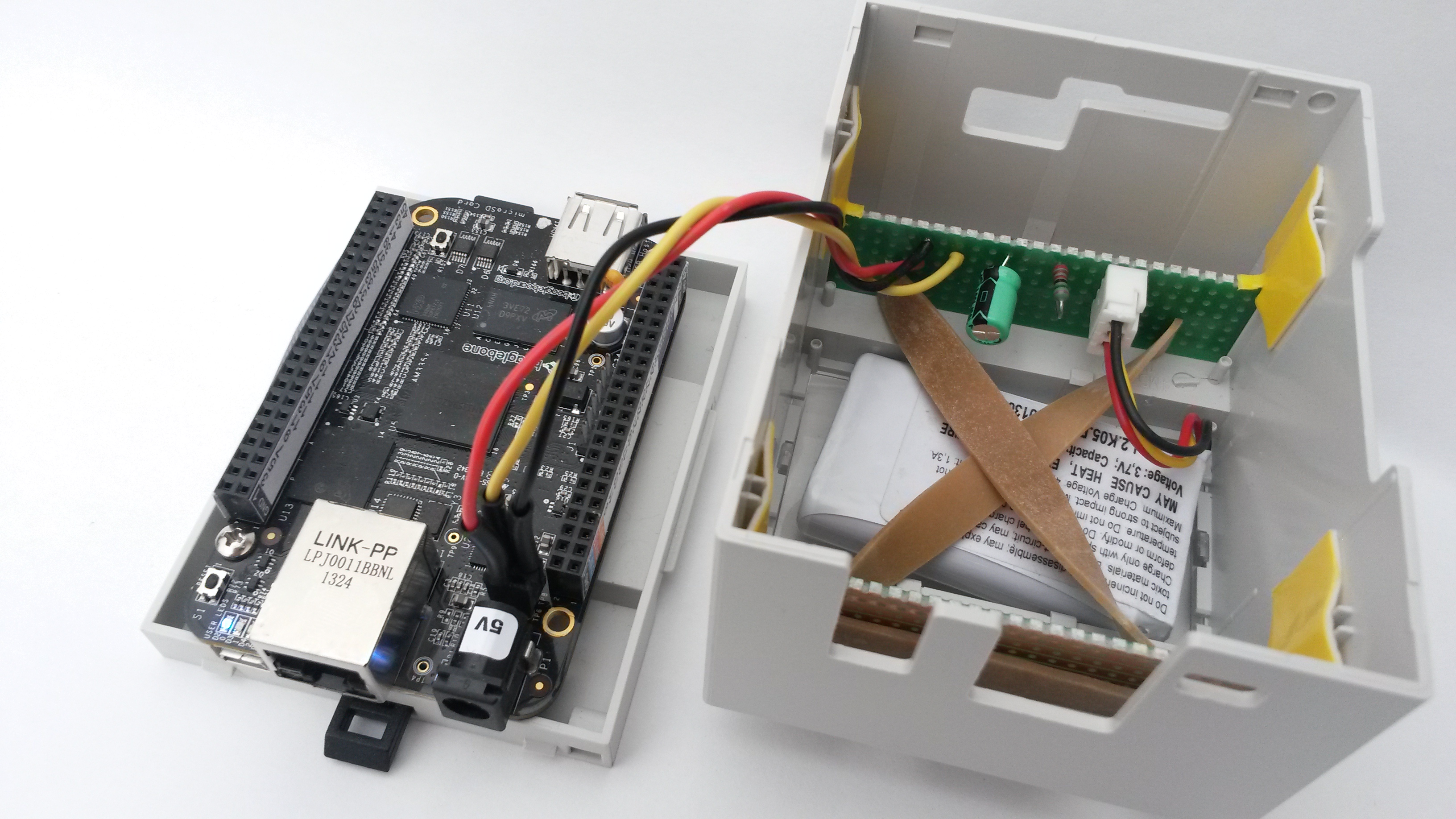
Connect the battery to the shrouded header and place the small board between the enclosure sides and available notches. Place the battery cables into the cable notch.
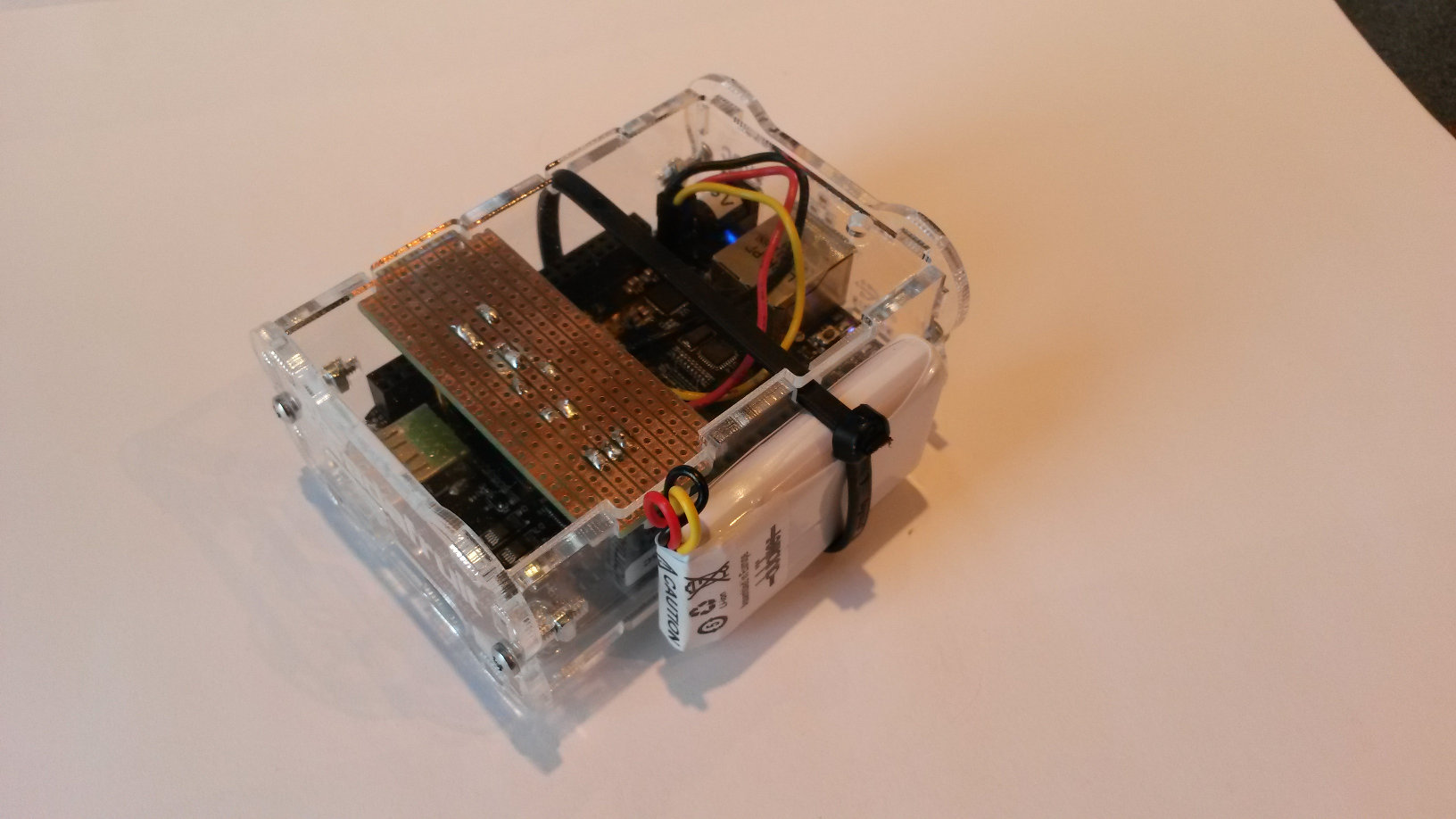
Place the battery along the enclosure side, where temperature is lower than on top. The Lithium-ion battery fastened on that side will probably last longer.
Don’t place it inside the enclosure! Eventual battery leaks may damage the BBB.
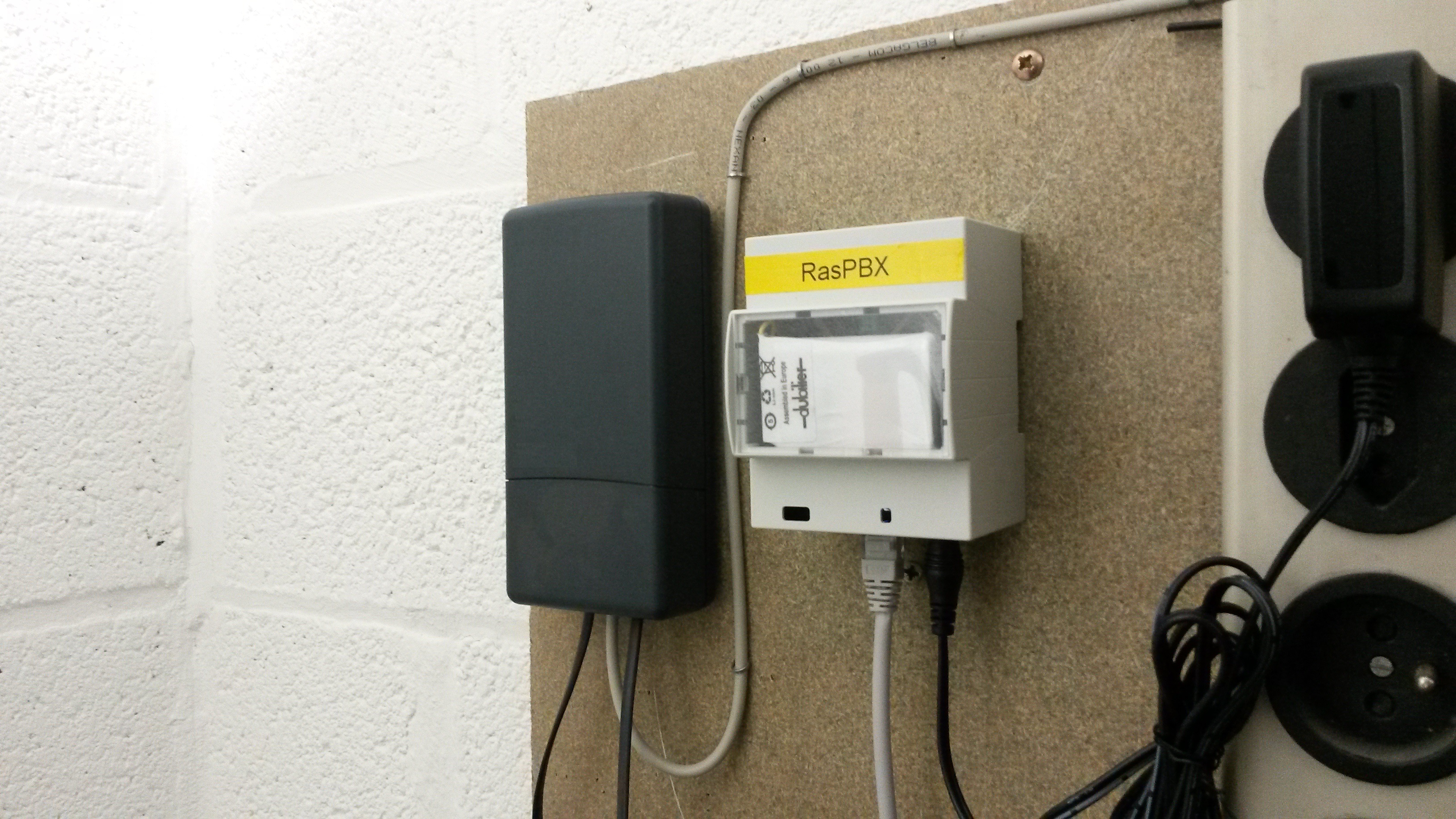
DIN rail enclosure for BeagleBone Black UPS
DIN rail enclosures are frequently used in home and industrial cabinets. The BBB + DIY UPS + battery can be very easily integrated in this 4 modules enclosure. Following pictures are self explanatory. Nevertheless it is recommended to read the DIY tutorial prior to build BBB UPS board.
Warning: if a µSD card is used on the BBB, shutdown the BeagleBone, switch off its power supply and remove the µSD card before assembling the equipment. It can be mechanically damaged when opening or closing the enclosure.
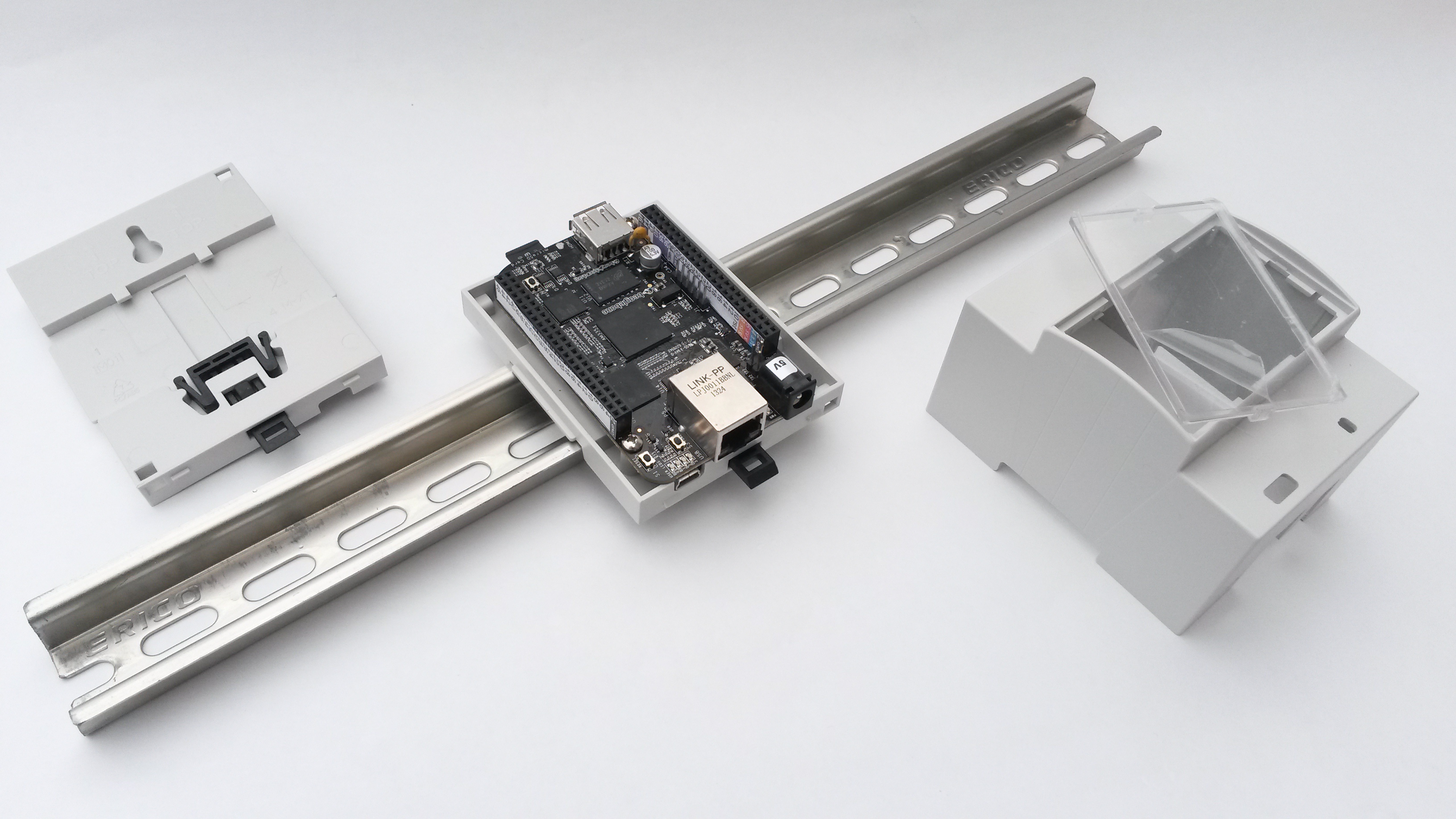
A wall mounting hole is provided on the enclosure backplane.
This picture in picture is a reference to the main DIY tutorial. Building the UPS board is straightforward, though it is necessary to use a crimp tool for the “2+2 way” crimp housing. A cheaper solution will be used in the following steps because a good crimp tool is generally expensive.
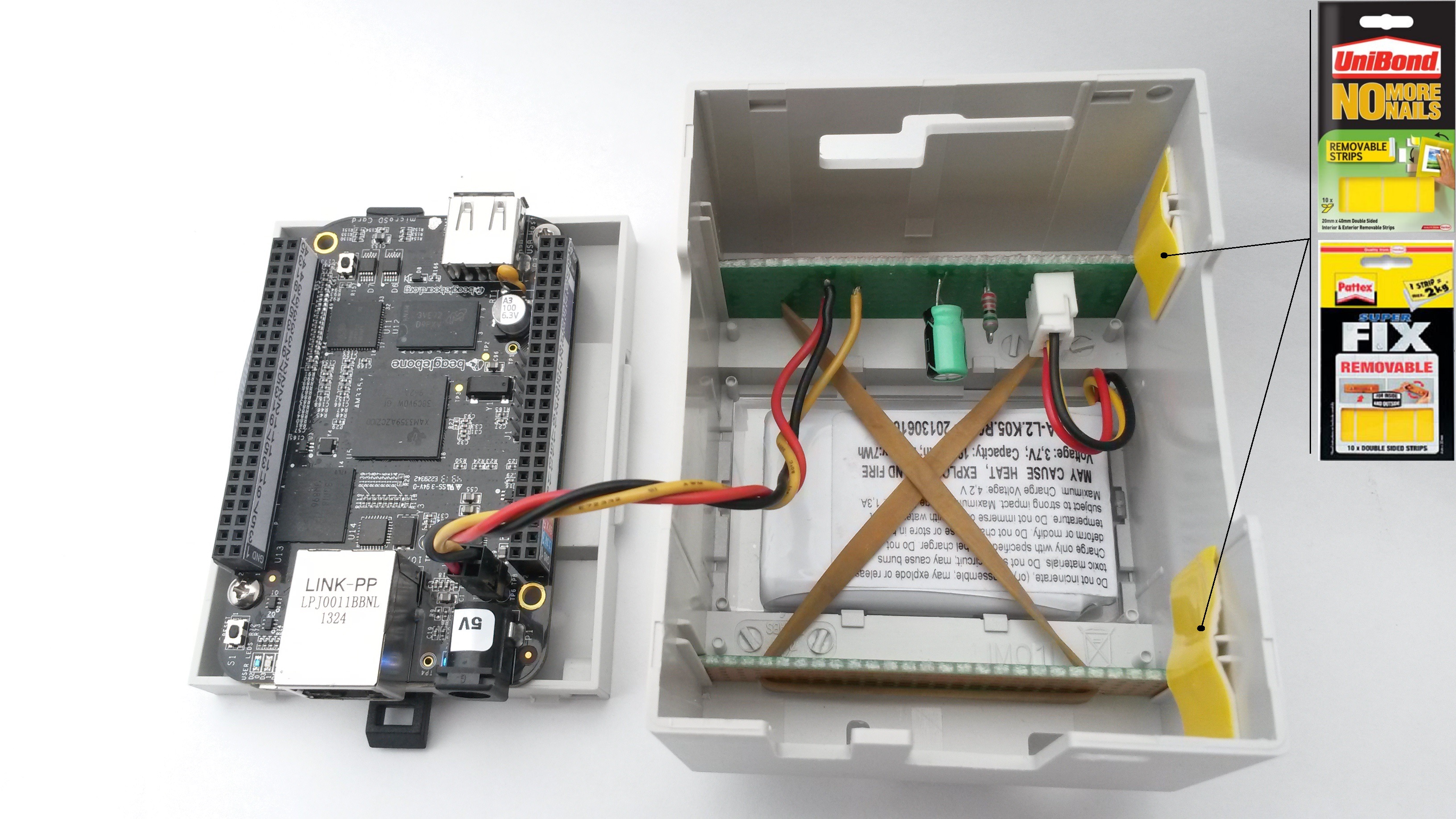
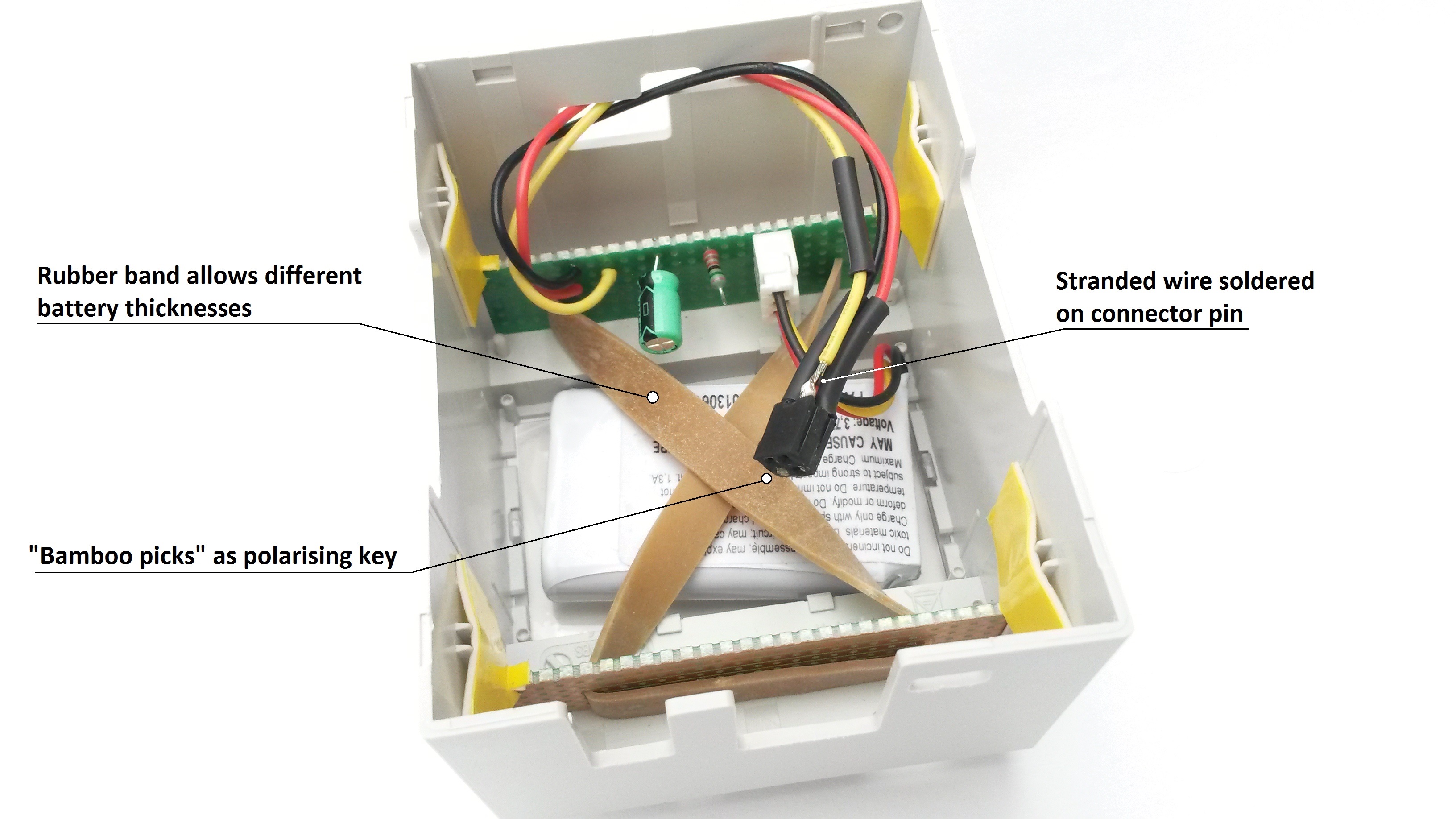
The two small boards may not move in the sliding guides . Placing removable stickers gives good results (see picture). Removable acid-free “montage” glue may be used. Placing one small glue dot, between the top of the board and the sliding guide, is sufficient . The drawback is that removable “montage” glue have long drying time. Not to forget is the rubber band. It enables use of different battery thicknesses.
As mentioned above, crimp tools are expensive and correct “2×2 way” connectors are rarely sold in electronic shops (connectors matching the small place available on the BeagleBone Black). But expansion connectors similar to those on the BeagleBone can often be found in these shops. Using a small saw, a “2×2 way” connector can be easily built. Stranded wires can than be soldered on connector pins. Check the numerous pictures in this DIY to solder these wires at the correct connector position.
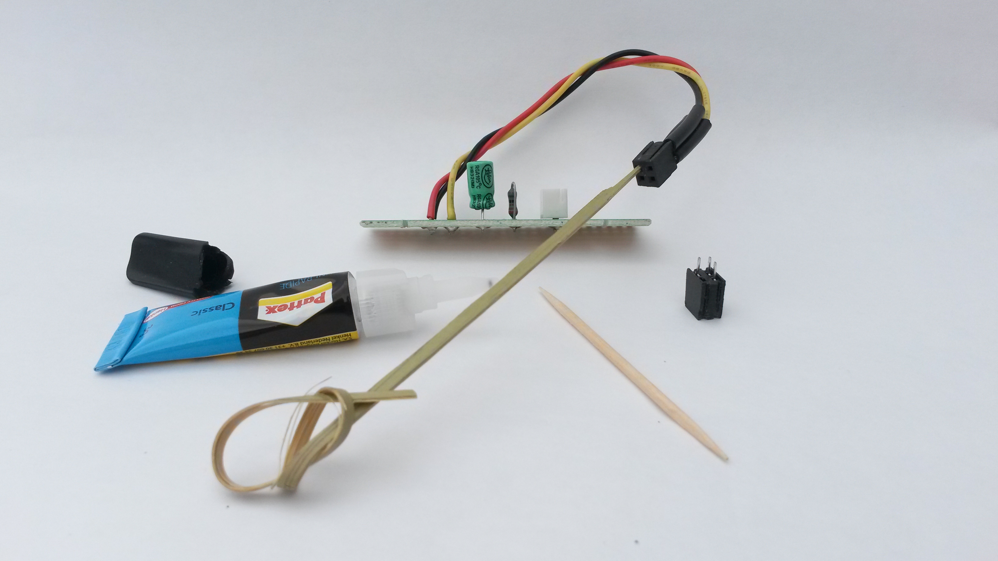
A wood toothpick or better a bamboo knot pick with some glue at one end is a convenient polarising key. A metal file can help getting the right bamboo pick size if it is too large to fit in the connector. Magnify the picture to precisely know where to stick it. Check also the following pictures to avoid any mistaken. Instant glue doesn’t allow wrong positioning.
Before plugging the connector on the BBB board, a 3 pins header needs to be soldered on the board. The bridge to solder on the BBB solder side is not to forget. The main DIY tutorial gives some tips to place this header. A nail file is used to achieve this task.
Suggestion: as dust may fall on enclosure top, protecting all three connector (µSD, HDMI, USB) from dust is highly recommended.
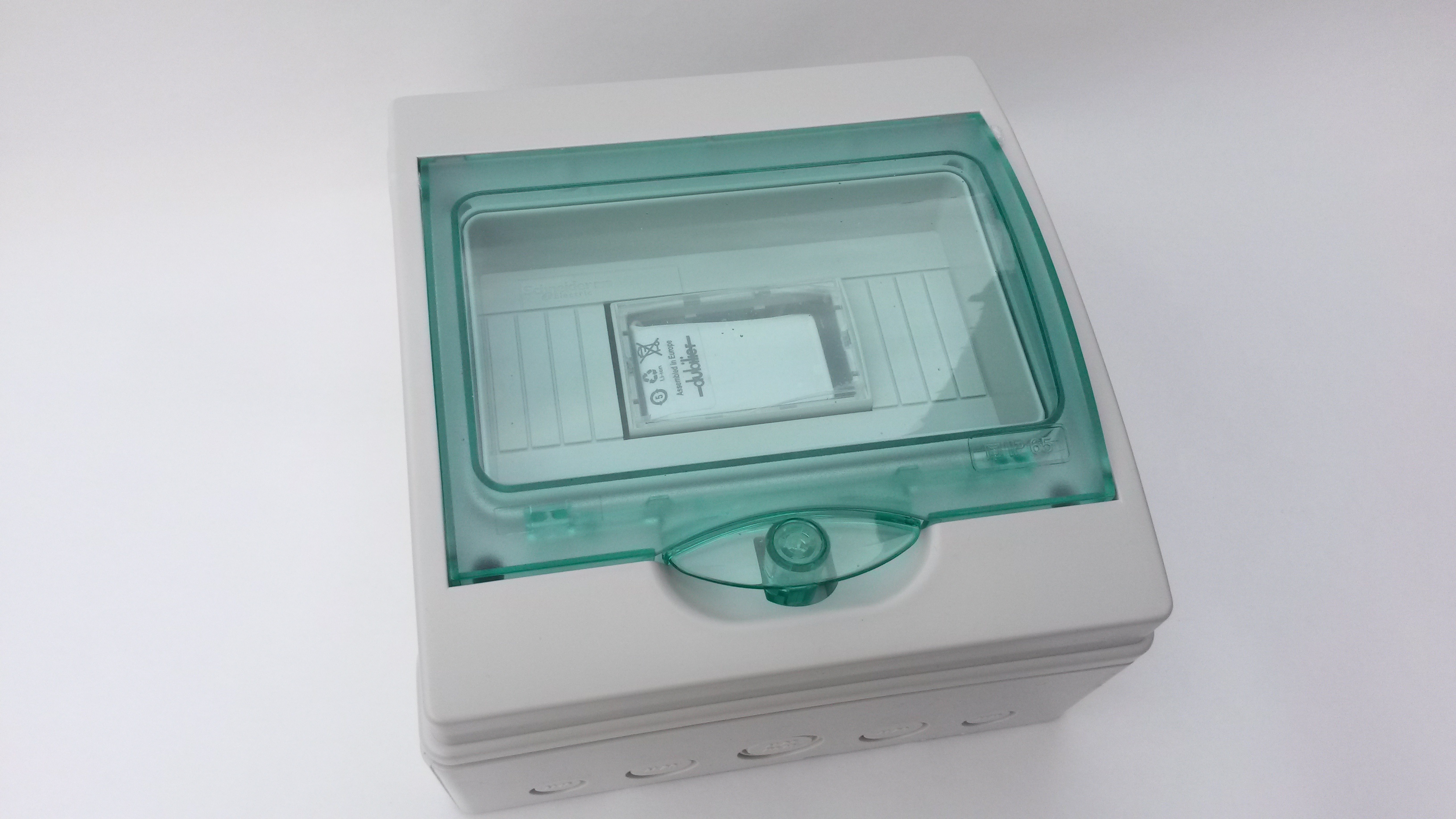
“Kaedra” modular mini-enclosure from Schneider Electric is IP65.
Pingback: วิธีสรŭ...
Pingback: Link: Uninterruptible Power Supply (UPS) for BeagleBone Black – a DIY Project » TechNotes
Hi! Thanks for this manual. But I have a problem. At first I was acting on instructions element14. I used 6000 mah Chinese battery from the tablet and chip U4 TL5209 burned. Please tell me how to use my battery properly. I am unable to order the battery Panasonic.
The TPS65217C power management IC on the BBB has a maximum rating of 3000mA for battery input and a recommended maximum of 2000mA. The element 14 tutorial also suggests a 700mA to 2000mA battery.
Hello Ivan,
Sorry that you burned a regulator on your BBB with Element14 instructions.
But that is precisely because Panasonic battery datasheet was matching TPS65217C PMIC (Power Management Integrated Circuit) requirements that I used it to built this small UPS.
Check these requirements page 28 of the Texas Instruments tps65217c datasheet.
Most 3.7V Li-ion or Li-Polymer have only 2 leads. It’s probably the case with your 6000 mAh battery.
So I suppose you own a 3.7V Li-ion battery with two leads ?
This kind of battery has certainly onboard security circuit with integrated thermistor or separate security PCB that is placed beside the battery . But in that case, you cannot connect one of the thermistor pole to BBB TP7 connection because the third lead (thermistor) is missing. Element14 instructions suggest to solder a 10 kOhm resistor to simulate this thermistor but a warning tells: “you may or may not wish to do this”.
That’s what I didn’t wish to do. Without direct NTC connection, the PMIC is not aware of the battery temperature. That’s why I modified slightly the circuitry and used a different battery type.
In most case that’s perhaps not a problem to put a resistor simulating the thermistor because it seems that the 1400 mAh battery used in Element14 instructions kept a resonnable temperature (Shabaz writes:…I have been using it daily for three months and the battery is always cool to touch). Nevertheless, that’s not the way the onboard TPS65217C is managing power and security. Element14 topic doesn’t describe rising temperature value during charging process. Temperature is, in this case, always rising.
The other issue, in Element14 instructions, is the SMD resistor soldered between TP7 and TP8. In case of incorrect soldering method, the TP8 connector pin may apply a mecanical stress on the 75 kOhm resistor when battery connector is plugged in or removed. The mechanical stress can change the resistor value if it’s damaged during these operations. Shabaz (Element14 instructions) soldered certainly correctly the SMD resistors (also the 0 Ohm resistor). He probably takes care when connecting or disconnecting the battery and he assumes that his battery is “healthy”. I prefer to think about the worst case in order to prevent users to get fire in their home. That’s the reason why I used a separate small PCB
I had a look at Farnell’s web site and discover that both 1200 mAh and 1950 mAh are temporarly out of stock. I can understand that it’s a problem for the UPS circuit as most Li-ion or Li-Po batteries are sold with 2 leads.
I don’t know your 6000mAh battery specifications, so you must be careful when trying to connect your battery.
I would try to solder an NTC parrallel ( electrically parrallel ) to the 75 kOhm resistor on the small PCB (DIY tutorial).Extension leads length could allow to attach this NTC to battery body. Why this complicate solution ? Batteries may not be documented when embedded in tablets! I want to ensure safety because these batteries may cause heat, explosion and fire if not connected with the correct circuitry .
I know, it is not an easy task to get these NTC. Local electronic stores don’t use to sell these passive devices.
I made extensive search to find a electronic distributor selling worldwide to private user. It seems that the following compagny sells quite everywhere: http://www.reichelt.de
They sell 10 kOhm NTC but transport costs may quickly rise for foreign countries
I wouldn’t use the white shrouded header type B3B-XH-A on the small PCB. It has anyway three connections and is useless for 2 leads battery.
So please follow the general DIY UPS guidelines
1) Power OFF your BBB
2) As previously mentionned use a 10 kOhm NTC that matches TPS65217C requirements for the NTC specifications at page 28 of the datasheet. If it is the case, connect two extension leads to it and solder them so that the NTC is connected parrallel to the 75 kOhm resistor. Caution: when the small DIY PCB is back in place in Adafruit enclosure, the NTC must be tied to the battery with a sticky isolating tape. That’s the only way to ensure proper temperature sensing
3) Check your cabling.
4) Depending of the solution you choose (Red, yellow, black wires soldered on the BBB or crimp housing type M20-1070200 + header soldered on the BBB board), connect the PCB wires (red, yellow, black) to PT5, PT7 and PT8.
5) Find a sytem that enables you to easely connect or disconnect the battery+ wire to the BAT+ copper strip on the small prototyping PCB.
6) Also connect the battery- (minus) wire to the GND copper strip on this PCB with the same system.
7) Power ON your BBB with 5V power supply and depress power button if the BBB didn’t start automatically (may be the case with some older BBB rev version).
8) If everything was correctly done, the onboard TPS65217C chip will begin charging the battery.
Bear in mind that these instructions were not yet tested with a two leads battery and there is no warranty that you will reach the result you expected. Also don’t put the battery inside the enclosure but on side of it.
Last but not least, remember that this small UPS will not power the 5V USB port when “battery mode only” is running.
Kind regards.
Michel.
PS: if I have some time in the following weeks I’ll try to build a UPS with RS-Components battery order number 791-6460 (12,38 EUR) and will check the above mentionned NTC. That could help most private users to more easely build BeagleBone Black UPS.
Hi Michel,
did you have the time testing the above mentioned circuit with a NTC and two wire batteries?
Hello Hannes,
Yes I could test a circuit with an NTC and a two wires battery but not with the above mentioned battery and not with the same small PCB that you can see in the DIY project.
Why ? Because it seems difficult to get some of its components for private people.
Crimp housing, crimp socket, connectors, even two wires battery are difficult to find. So I decided to get rid of most connectors that were part of the first project. For this new circuit, I just bought the 2 wires battery, 580 mAh 3.7V, from a “hobby shop” (mini RC helicopter spare part). My local electronic store provided the NTC. Also have a look at: http://www.reichelt.de for 10KOhms NTC with B Value= 3977 K
Instead of writing a long text about this new small circuit, I ‘ll try to take some pictures of it and post them on this forum if you want it ?
Kind regards
Michel.
Hello Michel,
thank you very much for your answer. I had the configuration without the NTC running for some days. I have trouble with my BBB but it is not related to the battery management (even works with the battery attached, but does not when only powered from the mains).
It would be great to see some pictures. Thanks in advance,
Hello Hannes,
Sorry to respond so late but I am quite busy at the moment. I really want to give the most complete information about this UPS topic
In order to help private people to get components at a reasonnable price, and get at the same time a Li-ion battery, I am still trying to find a distributor able to sell outside its own country. Distributor like Sparkfun doesn’t sell Li-ion battery in all points of sale. GoTronic doesn’t sell in foreign countries because of IATA Dangerous Goods Regulations related to lithium batteries. RS-Components doesn’t sell to private people. Some private owners of a BeagleBone Black have limited access to Farnell distributor in a couple of countries…
http://www.conrad.de in Germany sells batteries and also NTC but a bit expansive for what is to be measured. No need to get precise temperature measures. Important is to stop charging when temperature is too high.
I got all passive components from http://www.reichelt.de (specially the NTC). They sell outside Germany but they don’t sell 2 leads Li-ion batteries with correct capacitance (+/- 2000 mAh). Anyway they do provide a SANYO 18650 PCB (Li-ion – 2600 mAh) rechargeable battery without leads (price: 11,13 EUR). Buying a battery holder HA 1X18650 SA can solve the problem (price: 1,83 EUR). Correct wire size should connect the battery holder to the small PCB. Isolated wires from a defective PC power supply may be used for that task.
So stay tuned for the tutorial.
Kind regards
Michel.
WARNING: The modifications presented here can destroy your BBB when not done carefully! The authors of this article are not responsible for any hardware defects that might occur when implementing these modifications. BeagleBone Black power supply MUST be removed before working on it
COMMENT: don’t be astonished to get other prices when buying devices from this BOM. In reality Reichelt applies specific VAT rules related to country destination. For example the JUMPER 2,54GL SW will cost (incl. VAT) 0,04 EUR in Germany, 0,041 EUR in Belgium and 0,042 EUR in Danemark ! Bear in mind that Reichelt requests order for a minimum of 10 EUR and variable transport costs depending on country destination. With items quantities listed in the first BOM part, you can build a least five BBB UPS (excl. battery 18650, excl. battery holder and excl. battery holder leads).
If you use yellow and black insulated wires,from this BOM, connecting NTC to small UPS PCB, you will also need to use matching shrink tube 1,6 mm black.
If you use, as I did it, multi-stranded wire AWG 20 ( http://en.wikipedia.org/wiki/American_wire_gauge ) from an old defective PC power supply, don’t waste your money and simply don’t buy both insulated copper wire packs and shrink tube 1,6 mm. But keep shrink tube 4,8 mm as you will use it for bigger wire size (AWG20 for exemple).
If, you don’t own solid wire (single core wire) to build the two bridges on PCB, just use the resistor remaining leads or capacitor remaining leads to build these bridges. A small shrink tube can insulate them before soldering. For the purpose of this small UPS topic, I used colored wires related to BAT+ voltage (red) and GND (black) but, of course, both could have the same color.
In any case don’t use wires from this BOM to connect a battery holder to the small PCB mainly for safety purpose (wire size, insulation thickness and rated temperature withstand).
The best choice for a battery holder would be silicone rubber insulated wires but they are difficult to find in small quantities and are also expensive.
Don’t hesitate to put some shrink tube on NTC leads and separately on battery leads to protect them from cutting enclosure edges (Adafruit enclosure). Use a metal file to slightly round enclosure cutting edges
Items in the list can be checked on http://www.reichelt.de .
Just fill the “search field” on that web site with “item number” from the above first column list (copy and paste).
If you do know other distributors that sell also multi-stranded wires AWG20 yellow and black in small quantities, don’t hesitate to post a comment on this site.
It took me quite a lot of time searching a distributor selling almost everywhere in the world to private people. I gave up searching as I found this one, but I suppose that Reichelt is not the only one.
http://www.elv.de is also well known and seems to sell outside Germany but their web site is displayed only in German. Take care with “rechargeable battery”, it’s called “Akku” in German. This company sells a 3,7V Li-ion 18650 sized battery wherelse I bought the 3,6V labelled version by Reichelt. This 3.6V battery withstands anyway the 4,2V max charging voltage (datasheet in German). There is a typo related to the battery internal resistance in this datasheet. It should be 151 mOhm and not 151 MOhm. This 2600 mAh Li-Ion battery keeps the board powered for more then 7 hours when running idle most of the time. The following picture shows the first prototyping board with a 3,7V 580 mAh Li-ion battery.
For safety purpose, remember that soldering battery leads will be done in the final soldering step .
Bear in mind that this small PCB is a DIY prototype. I am not very satisfied with its mechanical stability inside Adafruit enclosure. A better design should be to enlarge the board, put a second header and a jumper near Adafruit enclosure side to mecanically balance the PCB. Enclosure top cover should then better maintain it when closed.
HOW TO
Two notches in a small prototyping board (continuous strip, hole spacing: 2.54 mm x 2.54 mn) (0.1 in x 0.1 in) are made with a small saw. Counting the hole number is an easy method to locate component position. When proceeding, two copper strips must be cut in the middle between holes as shown on above picture. A board corner needs to be removed for safe soldering process (size of 2×2 holes).
Before soldering components, verify that no tiny copper parts may fall from the small board onto the BBB when installed (possible damage!!). If necessary, use the metal file to carefully remove copper parts that the saw didn’t correctly cut. Clean the board when done.
The board itself will be populated with a 75 KOhm resistor, 10 µF electrolytic capacitor, NTC leads, BAT+ and GND bridges .
The following passive components will also be used and are rated 3A:
– 2,54mm (0.1 in) pitch DIL Vertical Socket
– 2,54mm (0.1 in) pitch header
– 2,54mm (0.1 in) jumper
Jumper is shown in one of the last pictures. It will be removed when battery is not in use and BBB mains supply disconnected. That is safe to avoid battery discharge. Even if not used, charging battery from time to time is recommanded.
If other components are used, it is safer not to operate components rated less than 3A .
In fact, charging current won’t probably exceed 500 mA. BBB consumption will probably be +/- 320 mA running RasPBX (with network connection only) but safety is a major concern. This UPS is mainly built to keep a running RasPBX during and after power outage (no data corruption).
In order to cut a 2×2 socket, remove 2 pins before cutting with the saw as described on left picture. When done, one header pin is removed from the small socket as described on right picture. It is suggested to immediately place a polarizing key on top of this socket in the space left by header pin (see following picture). A wood toothpick with some glue at one end will easily fit in it. Don’t force it in the socket. After glue drying time, cut and remove wood toothpick. Doing this immediately will hopefully prevent future wrong socket positioning on PCB before soldering.
Electrolytic capacitor needs its minus pole to be connected to GND copper strip. Check its “minus” sign on it before soldering.
CAUTION: battery leads without connector has a serious drawback. Battery is generally loaded when leads are soldered on the PCB. This can cause personal injury during soldering process if not done carefully. Even if feasible, soldering battery leads is not a safe choice. If no other solution is available (for example using an empty battery holder with leads) follow these steps:
– If possible wear safety glasses before doing the job.
– Before soldering battery leads, make sure that all other components are correctly soldered on the PCB (including NTC leads)
– Battery “plus” lead (+ sign) is then soldered first on PCB (battery red lead in general) meanwhile battery “minus” pole (- sign) is isolated from any PCB strip.
– Check if neighbour copper strip, that has to be left isolated from power supply (see one of the previous picture comment), has not been accidentally soldered to battery “plus” copper strip .
– Check also if neighbour GND copper strip has not been accidentally soldered to BAT+ copper strip. If possible, isolation measurement should be done with an Ohmmeter. If a short circuit has been detected, this fault has to be repaired first.
– After this test and eventually repair, battery black lead (minus pole) should be soldered on the most outer PCB hole as shown on above pictures. The PCB corner was removed specially to avoid short circuit between “plus” and “minus” pole during soldering process. That’s why BAT+ pole must be soldered and checked before soldering BAT “minus” pole (GND).
The PCB is just plugged into the 3 header pins to mount on BeagleBone Black (see picture).
Tip: a nail file is used to smoothly round the header pins edges on their solder side, so they easily fit in BBB holes (TP5, TP7, TP8 holes). Also not to forget is the bridge to be soldered between TP5 and TP6 (on BBB solder side).
IMPORTANT: DO NOT TRY TO DRILL LARGER HOLES. This will damage the BBB because it is probably built with a multi layer PCB. Existing metal coating, within the holes, builds electrical conductive connections between different layers and may not be removed by drilling larger hole diameters.
ADVICE: I discourage soldering the small black socket onto BBB board and mating header on the small UPS PCB. Socket pins easily fit in BBB holes and header pins unhappily not. This other way of building the UPS could be attractive ! But if this method is used, the header, powered by battery voltage, could inadvertently touch components on the BBB board and destroy them, specially if the jumper is left on the header (see jumper on last picture). Soldering the black socket on the small UPS PCB is safer.
Jumper is not plugged into PCB header until all components are correctly installed.
Correct temperature sensing is a safety concern. It is suggested to put some glue between NTC isolated leads and battery body, not onto NTC itself. An adhesive tape may stick them together during glue drying time.
Barrel connector from power supply is connected to BBB (not shown on this picture) , than power supply is connected to mains, jumper is plugged into PCB header. Depressing BBB power button starts the device.
Building the BBB UPS with an empty battery holder, instead of directly soldering battery leads on the PCB, is safer.
When using battery holder, take care of battery holder leads colors. Battery + and – signs are available inside the battery holder. Be sure to solder red lead (BAT+) on the correct battery holder termination.
Important: as the PCB stability inside the enclosure is not correctly assured, it is suggested to make 2 notches in Adafruit enclosure side with a metal file and build this cable assemby as described on picture.
CAUTION: You may want to use a hair dryer to shrink 4,8 mm tubes without directly blowing hot air on BBB components, battery or PCB components. Use home made deflector to avoid any dammage. Mind your fingers !!
Battery holder has snap-on feature. If you want to use it, three holes need to be done in the Adafruit top cover. (2 holes for the snap-on feature and an additional hole to avoid wrong positioning). But Ty-Rap may also be used instead.
Finaly the way battery is inserted in battery holder is the most important step to avoid BBB damages. So place battery + pole in the correct position !!!
Battery leads tied up.
Battery is automatically charged when mains power supply is connected.
Hi Michael,
thank you very much for your update!
Herzliche Grüße
If USB port doesn’t get power, then how to run a 3g modem for asterisk when mains power fails? Need to arrange 5v power separately?
Hello,
I wouldn’t try to use a separate 5V power supply. Supplying 5V from a 3.7 Li-ion battery and being able to charge the same battery is not an easy task. I mean this is not anymore a DIY project.
I would try a commercial BeagleBone Black UPS if I had to use an 3G modem.
Have a look at http://elinux.org/Beagleboard:BeagleBone_Capes
Searching on Google for “BeagleBone Black UPS” will also provide some results.
Nevertheless I never used these 5V UPS. So I cannot tell you if one of these would suit your needs
One more word about UPS and 3G modem: I encountered a power outage a month ago and tried, after an hour, to use my smartphone to get information from the grid operator . Unhappily the cell phone tower antenna suffered from the same power outage and couldn’t provide connections to Internet.
My main concern to use the DIY BeagleBone Black UPS is to keep a safe running RasPBX with an uncorrupted SD card
Kind regards
Michel.
Thanks for the tutorial.
My BBB seems to be shutting down correctly when it is fully boot up. But if it looses power during the boot up process it shuts down immediately without switching to the backup battery first. Could you help me understand what is causing this and whether I could program the BBB to switch to back up power in any state?
Thanks
Hello,
Sorry for my late response !
1) Loosing power during boot up process is statistically unusual. Despite my efforts, when RasPBX is running, powering off AC supply has no effect on the BBB when running Ubuntu 14.04.2 , Asterisk 11.17.0, FreePBX 12.0.57 with a DIY UPS. Even during boot process when AC PS is removed (battery attached), I cannot reproduce this behavior. Which Linux distribution are you running ?
2) If you are running LXDE Debian version, a shutdown occurs indeed. Searching on the following link with the words “another battery question” will give you some guidelines to avoid this shutdown:
http://beagleboard.org/Community/Forums
As I am not skilled enough to dig in Uboot, I would use a work-around to solve this issue. Applying AC mask in tps65217c INTERRUPT register 0x02 will prevent the system to shutdown. But that could be also dangerous. For exemple, if the BBB is left running on “battery only” mode, a brutal breakdown occurs when battery is empty (data corruption). Use this method at your own risk !.
If you anyway want to give it a try, download the tps65217c.pdf file (link in the DIY UPS tutorial) and check page 44. When setting data bit D5 to 1 in INTERRUPT REGISTER 0x02 , no interrupt will be issued when removing AC power supply. In order to keep also data bit D7 equal to 1 when writing in this register, the following command will be executed:
i2cset -f -y 0 0x24 0x02 0xA0
check the result with following command:
i2cget -f -y 0 0x24 0x02
The response must be: 0xa0
Check the “man” pages related to “i2cset” and “i2cget” to get correct command format as blank space don’t correctly display in this page.
It will normally prevent the system to shutdown when AC power is removed. You’ll have anyway to build a small script to safely shutdown the system after a “certain time” when running “battery only” mode. Note also that as soon as the BBB reboots, the INTERRUPT REGISTER is reset ! So you’ll have to run this command automatically if you wish to use this feature.
Keep also in mind that using a GUI will cause another problem when AC power is off. Keyboard and mouse are connected to the BBB via a USB hub. BBB USB interface won’t work in “battery only” mode (see warning in tutorial). As soon as BBB AC power is removed, you won’t be able anymore to use both keyboard and mouse even if the USB hub is separately supplied with AC power. Applying this method may have unexpected results on BBB behavior and applications running on the system. So again use this method at your own risk !.
Hope this help.
Michel.
Hello Michel and Gernot.
Thank you for an excellent tutorial!
Can you please explane why you use a 75kOhm resister in parallell to 10kOhm NTC with your 1950mAh battery?
Best regards
Daniel
Hello again.
I found out why you have a 75kOhm resistor in parallell to 10kOhm NTC. I datasheet page 31 they recommend to use 75kOhm resistor in parallell to linearize the temperature response curv.
Thanks
Daniel
Hello Michel,
Your pictures of the BBB UPS with 18650 are no longer available. Could you refresh it?
Thanks!
Hello Nuno,
Sorry to respond so late. I’ll do my best to check if I can insert them again. But I just want to warn eveybody about this “micro BeagleBone Black UPS”: I am not very satisfied with its mechanical stability inside Adafruit enclosure. The fact is that I encountered brutal shutdown when moving the cables. I noticed that the best UPS is the one of the main tutorial not the one of the micro BeagleBone Black UPS.
Anyway, I’ll see what I can do.
Michel.
The BBB is unfortunately suceptible to slowly rising supply voltage when powered on. It sometimes does not boot at all, which can be a serious problem after a power glitch.